
Learning Objectives:
Explain ultrasound physics relevant to EUS: piezoelectric effect, frequency, resolution, attenuation, echogenicity, doppler - color and spectral, aliasing.
Become proficient in “knobology”: the ability to obtain optimal images by selecting the proper probe, adjusting image mode, gain, time gain compensation, and focus.
Recognize common ultrasound artifacts including: reverberation, side lobe, mirror, shadowing, enhancement, ring down.
Basic Physics principles:
Probe emits ultrasound waves which detect depth of the object based on how long it takes the waves to return to the probe after being reflected by the object
Waves reflected back to the probe are called returning echos
Amount of returning echos depends on material and angle of insonance (angle that the ultrasound waves interact with the object)
Piezoelectric effect: the ability of the ultrasound probe to convert electrical energy into sound waves that travel through the body and then convert returning echoes back into electrical signals, which are used to create real-time images of internal organs, tissues, blood flow, etc.
Wavelength: the length of a single wave.
Short wavelength = high frequency (less depth but higher resolution of US image)
Long wavelength = low frequency (more depth but lower resolution of US image)
Frequency: the number of sound wave cycles per second (measured in megahertz). It affects image resolution and depth of penetration. Higher frequencies do not penetrate the body as deep but provide higher resolution images, while lower frequencies penetrate deeper into the body but produce lower resolution images.
Resolution: the ability to distinguish between two closely spaced structures - higher resolution allows for more detailed and accurate images. Resolution improves at higher frequencies, helping to differentiate structures that are close together along the path of the ultrasound beam.
Attenuation: ultrasound waves get weaker as they travel through the body. This occurs due to absorption, reflection, scattering, and refraction of the ultrasound waves. Each medium in the body has a specific attenuation coefficient or speed at which it decreases the ultrasound wave intensity.
Bone and air have HIGH attenuation, meaning they quickly decrease the intensity of the ultrasound wave
Blood has low attenuation, fat and liver have slightly higher attenuation than blood
Impedance: how much a tissue resists the ultrasound wave passing through it. When there’s a big difference in impedance between two tissues—like soft tissue and bone—more waves are reflected back, which creates a brighter appearance. For example, the bright white line seen when scanning over bone is due to its high impedance.
Echogenicity: how bright or dark a structure appears on the image, based on how much sound it reflects.
For example, fluid-filled structures like cysts appear black (anechoic) because they don’t reflect ultrasound waves, while solid structures like bone reflect more sound and appear white (hyperechoic).
Doppler - color and spectral:
Color Doppler shows blood flow direction and speed as different colors overlaid on the image—can be used to quickly identify areas of normal or abnormal blood flow.
In color doppler, RED = TOWARDS probe and BLUE = AWAY from probe. These do not necessarily correlate with venous and arterial flow
Spectral Doppler (i.e. pulse wave and continuous wave doppler) provides a graph of blood flow velocity over time, allowing precise measurement of flow speed and patterns - useful for assessing valve function or vessel narrowing.
The Nyquist limit is the maximum Doppler shift (maximum blood velocity that the ultrasound system can measure without aliasing)
Aliasing is an artifact specific to doppler ultrasound - it occurs when the blood velocity exceeds the system’s Nyquist limit. This can make the Doppler colors or waveforms appear incorrect, or cause a “wrap-around” effect where the colors change abruptly.
Knobology and image acquisition:
Knobology: understanding and using the controls on an ultrasound machine appropriately to obtain the best possible image. Key controls include gain, which adjusts the brightness of the image; depth, which determines how deep the sound waves go; and focus, which sharpens the image at a specific depth.
Image Mode
B-mode (Brightness mode): the most common mode and default on the ultrasound machine - this is what creates 2D grayscale images of structures based on the strength of returning echoes
M-mode (Motion mode): shows the motion of structures over time along a single line - we use this in cardiac imaging to measure EPSS and TAPSE
Doppler (Color, Spectral)
Gain: controls the brightness of the image by adjusting the amplification of the returning echoes. Increasing the gain makes the entire image appear brighter, while decreasing it makes it darker. Proper gain settings are important—too much gain can make the image look washed out, and too little can make structures difficult to see.
Time gain compensation: allows you to adjust the brightness of the image at different depths. Since ultrasound waves lose strength the deeper they go, TGC allows deeper structures to appear as bright as shallow ones. This creates a more uniform image, so you can clearly see structures at all levels.
Focus: refers to the area where the ultrasound beam is the narrowest and image resolution is the highest. Adjusting the focus to the appropriate depth improves clarity and detail of the structure in question, making it easier to identify small or subtle findings. Proper focus placement is key for accurate imaging.
Transducer types
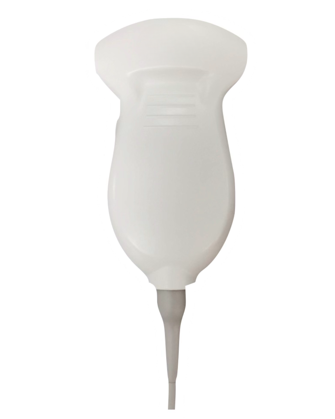
Curvilinear
Lower frequency, good penetration, moderate resolution. Great for abdominal, pelvic, and deep organ imaging

Linear
High frequency, higher detail, limited depth. Great for superficial structures such as blood vessels, soft tissue, pleural line, and MSK exams.

Phased Array
Lower frequency (similar to curvilinear probe) but smaller footprint, mainly used for cardiac imaging because it fits between the ribs.
artifacts
Reverberation Artifact: appears as multiple, equally spaced echoes caused by sound bouncing back and forth between two strong reflectors, such as the pleura (seen here) or a needle.
c/o John Elue, MD
Ring Down Artifact: appears as a continuous, bright vertical echo extending deep to a gas bubble, caused by resonance of trapped air. B lines (seen here) in thoracic ultrasound are caused by this artifact and phenomenon.
c/o Kevin Boubouleix, MD
Ring Down Artifact: appears as a continuous, bright vertical echo extending deep to a gas bubble, caused by resonance of trapped air. Air in necrotizing fasciitis (seen here) or bowel gas can also lead to bright lines extending deep, obscuring any structures below.
c/o Adam Roussas, MD
Shadowing: appears as a dark area behind a highly attenuating structure, such as bone or a gallstones (seen here), because the ultrasound waves are reflected and cannot penetrate the structure.
c/o Kevin Regis, MD
Mirror Artifact: creates a duplicated image of a structure on the opposite side of a strong reflector, like the diaphragm, making it look like a second liver.
Posterior Acoustic Enhancement: appears as increased brightness (hyperechoic) below a fluid-filled structure such as a cyst or bladder, this occurs because the ultrasound waves pass through fluid with minimal loss and create stronger echos below.
Edge Artifact: appears as a shadow-like line extending from the edges of a curved structure, such as a gallbladder or vessel. It occurs when sound waves bend (refract) at the edges, causing a loss of signal directly below them.
Side Lobe Artifact: occurs when off-axis ultrasound waves reflect off a strong reflective structure and are mistakenly placed in the main beam path, creating false echoes that are misplaced in the image.
Resources:
Malin and Dawson iBook Volume 1, Chapter 8: Physics
ACEP Sonoguide: Ultrasound Physics and Techincal Facts for the Beginner
Core Ultrasound: Basics
POCUS 101: Basic Principles of Ultrasound Physics and Artifacts Made Easy
POCUS 101: Ultrasound Knobology, Probes, and Modes Made Easy
The Ohio State University Ultrasound Interest Group: The Basics of Ultrasound
US Physics and Knobology Lecture by Geoff Hayden
Author: Ryan Abbott, DO (Class of 2027)
Peer Editing by: Christine Jung, MD-FDP